Chapter 5 - Liquefier Acquisition and Control Computer
Appendix
2. Helium Purity meter calibration for automated readings
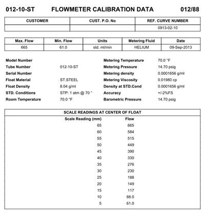
3. Helium purity meter rotometer calibration chart for helium gas: (mm -> ml/min)
4. Pertinent facts (conversions etc.)
6. Dahua Ethernet Camera Info: DH-IPC-HFW4300S
7. Relay board and computer control notes:
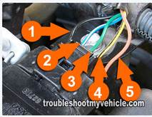
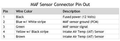
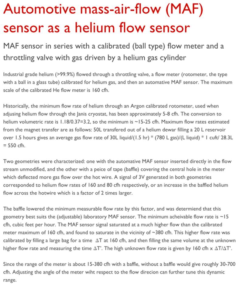
8. MAF sensor (Toyota Corolla 1.8L) wiring diagram:
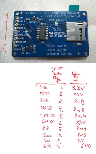
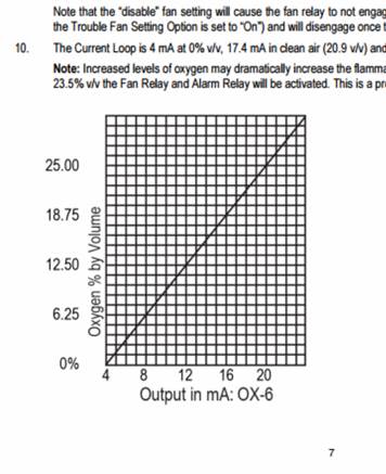
9. Arduino 1.8” TFT display wiring chart O2 Sensor calibration chart
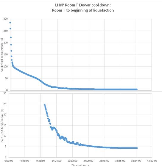
May, 2016: Cool Down of LHeP 150L Dewar from Room temperature to start of liquefaction
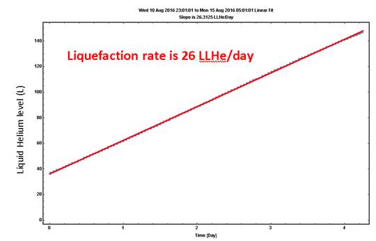
10. August, 2016: liquefaction raTe of Cryomech Liquid Helium plant 22
11. Mitigating bladder leaks ---- August-September, 2016: Dewar Blow off rates
12. Various items that should be implemented as of 5/22/2016
Peripheral files
View website PDF document
Hi-res video: Building a helium recovery system (5 minutes long)
YouTube video: Building a helium recovery system (5 minutes long)
List of many parts with prices and links [xls]
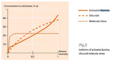 |
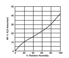
Activated alumina was chosen over silica gel, activated charcoal, and zeolites/molecular sieves. At low relative humidity, the case for recovered helium, zeolites are the most efficacious for adsorbing water. However, the extremely high bake temperature (>300C) makes regeneration difficult. Activated alumina is better than silica gel at low relative humidity and regenerate at relatively low temperatures, >150C. Also, the water capacity of activated alumina is high.
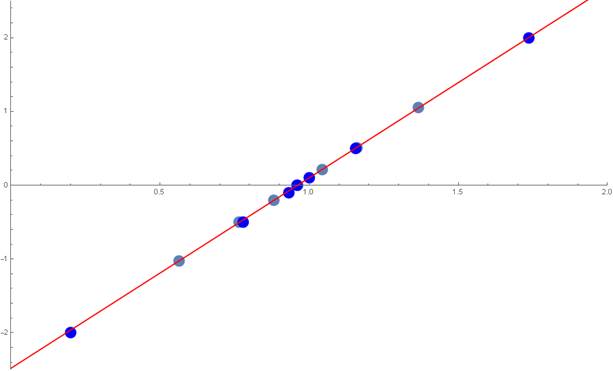
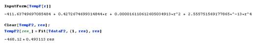
In the below graph, the abscissa is the analog output voltage from the helium impurity meter (V) and the ordinate is the impurity level (%). The zero is attained experimentally so only the slope is needed for impurity measurements. The red line is a least-squares regression fit with a slope of 2.583 %impurity/V.
Supplied by Harry Oyarvide on 5/9/2016, Omega Engineering, Inc., Application/Sales Engineer , Flow Department, Phone: 800-872-9436 ext 2536, hoyarvide@omega.com
· 0.2754 lbs liquid helium = 1 liter liquid helium, 1.777 lbs liquid nitrogen = 1 liter liquid nitrogen
· 1/2% per day of impurities for about 10LLHe in bladder; LN trap increased total purity in bladder by 1%/day
· conversions ~770 for expansion of liquid into gas at 298K ~ 76F (crymech says 754)
· 1 L LHe --> 27.3567 ft^3 gas, 1 L LHe --> 0.774656 m^3 gas
· “A” cylinder volume ~ 250 ft^3 --> 9 LLHe, 300 cuft cylinder ~ 11 LLHe
· 300K to 4K costs 74x the energy than to liquid-solid energy
· For 2nd stage cooling power of (1.5 J)/s, gas at 4.22K can be liquified at rate of (50.087 L)/day
· The cost of using only latent heat of vaporization of LN to precool Helium gas from room temperature to 77K = (1.28721 Dollars)/LHeLiters
· The power required to heat 100L of helium gas from 4.4K to 295K in 3 hour is (151.364 J)/sec
·producing a volume of gas equivalent to 8.65487 L of liquid helium. Note that for real mobile dewars, there exists thermal gradients from room T at top to 4.4K at bottom which will cut the power and volume of gas released ---- very approximately say half.
· To fill a 3.068 in^2 ID pipe that is 6 ft long with equal sized spheres of alumina requires
·14.7853 lbs of alumina, and can hold approximately 1.0 L assuming ~ 10% relative humidity
· The LN cold trap with zeolites is quoted as able to adsorb 1 Kg of air. Assuming N2, a flow rate of 23 LLHe/day and 5% impurity level gives 1.8 days run time.
· 14’x24’x10’; Bladder is 3400 cuft volume ---> 125 LLHe, .040" thick, 350 lbs; Extrapolation of test bladder leak rate ---> ~15 LLHe / year
· With LHeP compressor off, ~45L LHe inside 150L dewar, boil off averaged about 0.3 LLHe/hour over 21 hours
· From McMaster “Also known as instrumentation fittings (York), they are compatible with Swagelok®, Parker A-Lok, and Let-Lok fittings. “
· If water output > 126F measured by LHeP22, the compressor will shut down and produce an “error” (as opposed to warning). The compressor will stay off until user manually resets software. Note that for oil>130F or He>149F, the compressor will shut off.
· It took about 44 hours to go from Room T empty 150L dewar to producing measurable level of liquid helium accumulation in dewar.
· The level is sensitive to conditions in the dewar like pressure and whether cold head is on or off regardless of actual level. This variation appears to be about ~3L.
· An empty 150 L dewar with T=4K gas will be 150L*295K/4K ~ 14.5 liquid liters worth of helium.
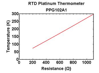
RTD PART NUMBER PPG102A1 (RESISTANCE VS. TEMPERATURE TABLE) _ U.S. Sensor Corp_files
ethernet jack in Phys Room 2315
3c241/3c242
Dahua
Model DH-IPS-HFW4300S-V2-0360B
PN 1.0.0.01.04.4847
SN 1G01D94PAU00231
MAC 4C:11:BF:CE:51:8F
Network Name: IPC
Login: <my UMD user ID>
Password:<usual lab password>
Login: admin
Password: <usual lab password>
phantom power through network
75' ethernet
gigabit switch
How to wire up the relays and computer so that devices remained powered down in case of power outages (and subsequent restoration of power):
The program will send a signal of either 0 or 1 to the relay, which will either turn something ON or OFF depending on the relay’s mode. The relay has two modes. Under both modes, the relay compares the voltage reading of the +5V output and the digital output from the computer.
· Normally Closed
o If the inputs are EQUAL, then the switch is closed and the device is powered ON.
o If the inputs are UNEQUAL, then the switch is open and the device is OFF.
· Normally Open
o If the inputs are EQUAL, then the switch is open and the device is powered OFF.
o If the inputs are UNEQUAL, then the switch is closed and the device is powered ON.
Normally the computer regulates the digital outputs against the +5V output. However, when it shuts down, this regulation stops and the digital outputs become equal to whatever the +5V output is (and this output is decaying in accordance with some capacitance time constant). Since we want the devices to shut OFF with the computer, this means we want the device to shut OFF when the voltage readings are EQUAL. This means we must use the normally open setting. (Otherwise, under normally closed, when the computer shuts down the voltage readings would be equal and the pump would turn on).
The computer also does not begin to regulate the digital output voltages until a program tells it to do so. This means that when the computer turns back on, the voltage readings are still equal and the devices remain off. This is also what we want.
Finally, under normally closed, if the power to the relay switches off, so does the power to the devices. This is what we want in case of a power outage. So our settings are:
· Normally closed
o 0V (=0) powers the device ON
o +5V (=1) powers the device OFF
(http://troubleshootmyvehicle.com/toyota/1.8L/how-to-test-the-maf-sensor-1 )
The refresh rate is every second. Analog input #0 measures the voltage across a metal film resistor that is grounded on one end. The O2 concentration current output from the wall mount O2 meter is copied from the spec sheets:
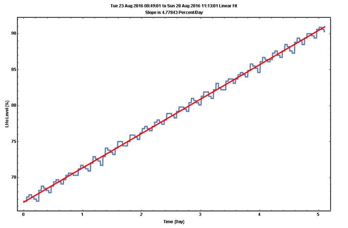
Since the bladder leaks helium at a rate of around 0.5 liquid liters/day, an order of magnitude larger than expected based upon earlier test bladder leak rates which agreed with the calculated bulk permeability of the material, it is not feasible to recover helium dewar blow-off into the bladder. The blow off of the dewars are specified to be less than 0.5 liters/day under the condition that the dewars are maintained at low pressre of around ½ psig.
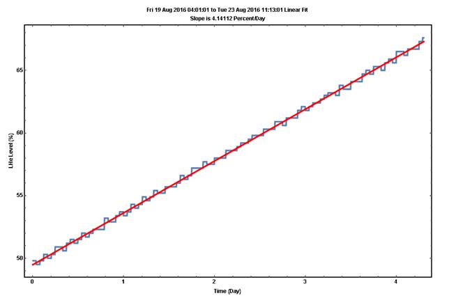
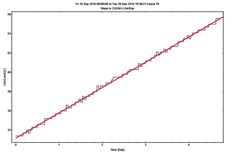
An alternative configuration is connecting the mobile dewar vent valve (with ½ psi check valve) directly to the cryomech liquid helium plant dewar. The following tests show this configuration. The cold head re-liquefies the mobile dewars helium blow-off into the 150L dewar. The blow off rate can be characterized by measuring the rise of the liquid level in the 150L dewar.
The following three test results show the blow-off rates under three configurations of the liquid helium plant:
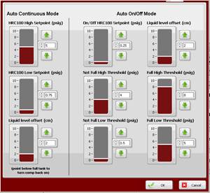
(1)Auto on/off mode, where the cold head turns on when the dewar pressure reaches 8 PSI and turns off at 0.5 PSI; results in 4.8 LLHe/day for both mobile dewars.
(2)Auto on/off mode, where the cold head turns on when the dewar pressure reaches 4 PSI and turns off at 0.5 PSI; results in 4.1 LLHe/day for both mobile dewars
(3)Auto-continuous on/off mode, where the cold head turns stays on and heater turns on to maintain the dewar pressure at 0.75 PSI; results in 2.6 LLHe/day for both mobile dewars
In all three conditions, note that the pressure in the mobile dewars is 0.5PSI higher than the 150L dewar due to the check valve.
For cryomech liquid helium plant configured at factory settings, blow off of the two dewars (each initially almost full, where 60L dewar has about 50LLHe and 100L dewar has about 90LLHe), into the 150L dewar cryomech is about 4.8 LLHe per day. Note that the graphs are mot labeled correctly here (Level was measured in liquid liters, not percent)
Leak testing the plumbing is most effieciently done by pressuring the pipes and using a soapy water mixture, brushed on the joints. If no bubbles appear within a minute or so, then the leak rate is insignificant for a helium recovery system.
· Interface computer with cyromech LHeP22 compressor in order to coordinate chiller with compressor on/off status
· Pump interlocks on lab manifold to prevent pumping on the bladder with the lab vacuum pumps
Possibly implement:
· A way to salvage/scavange LN from wide-mouth 240L dewar
· Mount 240L LN vent pressure regulator to the wall
· Replace scroll pump with sealed pump from He3 system.
Lessons learned: What I would do differently
· Connect a flexible line to the bladder flange instead of using inflexible PVC pipe
· Invest in a large motorized ball valve immediately before the bladder flange to better guard against under and over inflation conditions
· Use smaller diameter pipe for all helium lines --- it was very difficult to plumb all the pipe, contrary to the advice I received. I should not have engineered the system to recapture the helium from magnet quenches.
· Never do business with Quantum Technology --- A much better helium purity meter is now sold by Stanford Research that utilizes speed of sound instead of hot wire anemometry; The Quantum Technology cold trap was not engineered. I could have engineered it and built two of them fairly easily instead of paying an exorbitant amount of money for essentially welded stainless steel pipe.
· Maybe it would have been better to go to a compression system, but was much too expensive for our system when facilities costs are included